
This week our team focused on building a complete small CNC plotting machine from scratch: mechanics, electronics, firmware, and testing.
Our goal was not only to make it move, but to make it reproducible and clearly documented so another team can rebuild it.
We used a Raspberry Pi Pico (RP2040) as the controller, two stepper motors with TMC2208 drivers for motion, and one servo motor for pen up/down.
Firmware is written in MicroPython and controlled over USB serial commands.
> Attribution: This firmware is a remix of the PicoNC idea and workflow. We adapted the base concept for our machine with CoreXY support, pen-servo control, and a practical command set for drawing.
For Machine Week, we wanted a compact plotting machine that can:
We followed the Blot assembly workflow and adapted it to our available lab hardware:
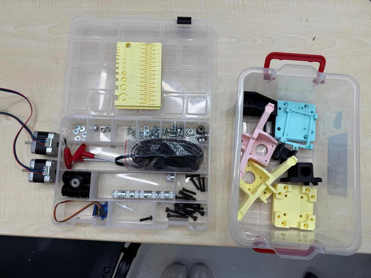
Figure 1. Used parts prepared before assembly.
We started by assembling the carriage using:
Detailed assembly sequence:
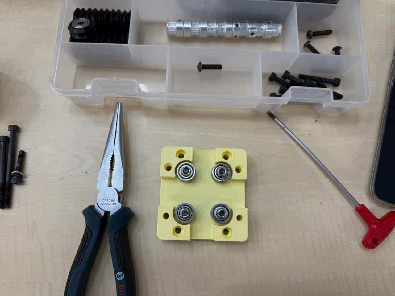
Figure 2. Carriage plate assembly with wheel hardware layout.
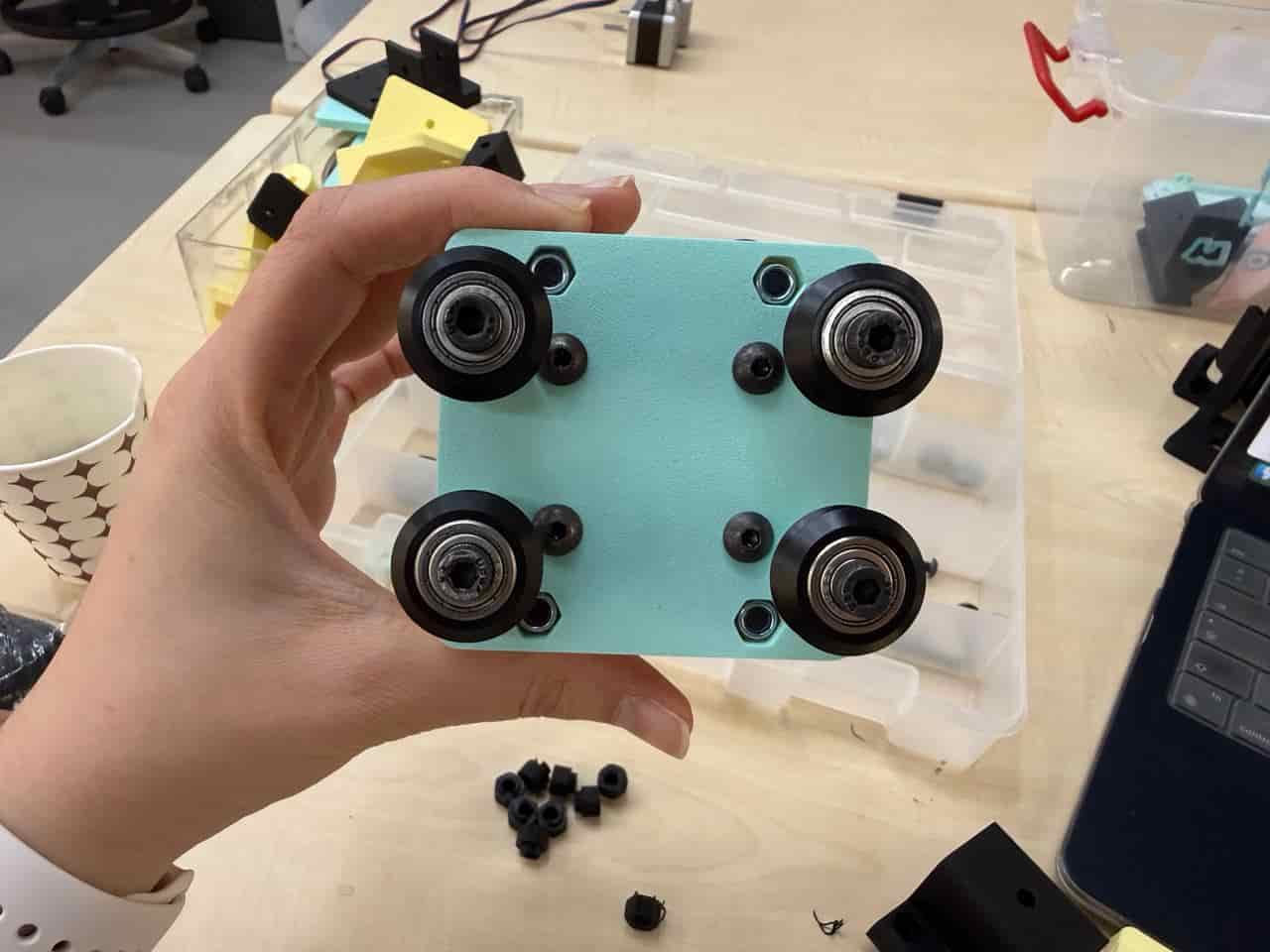
Figure 3. Bottom side of the carriage after wheel installation.
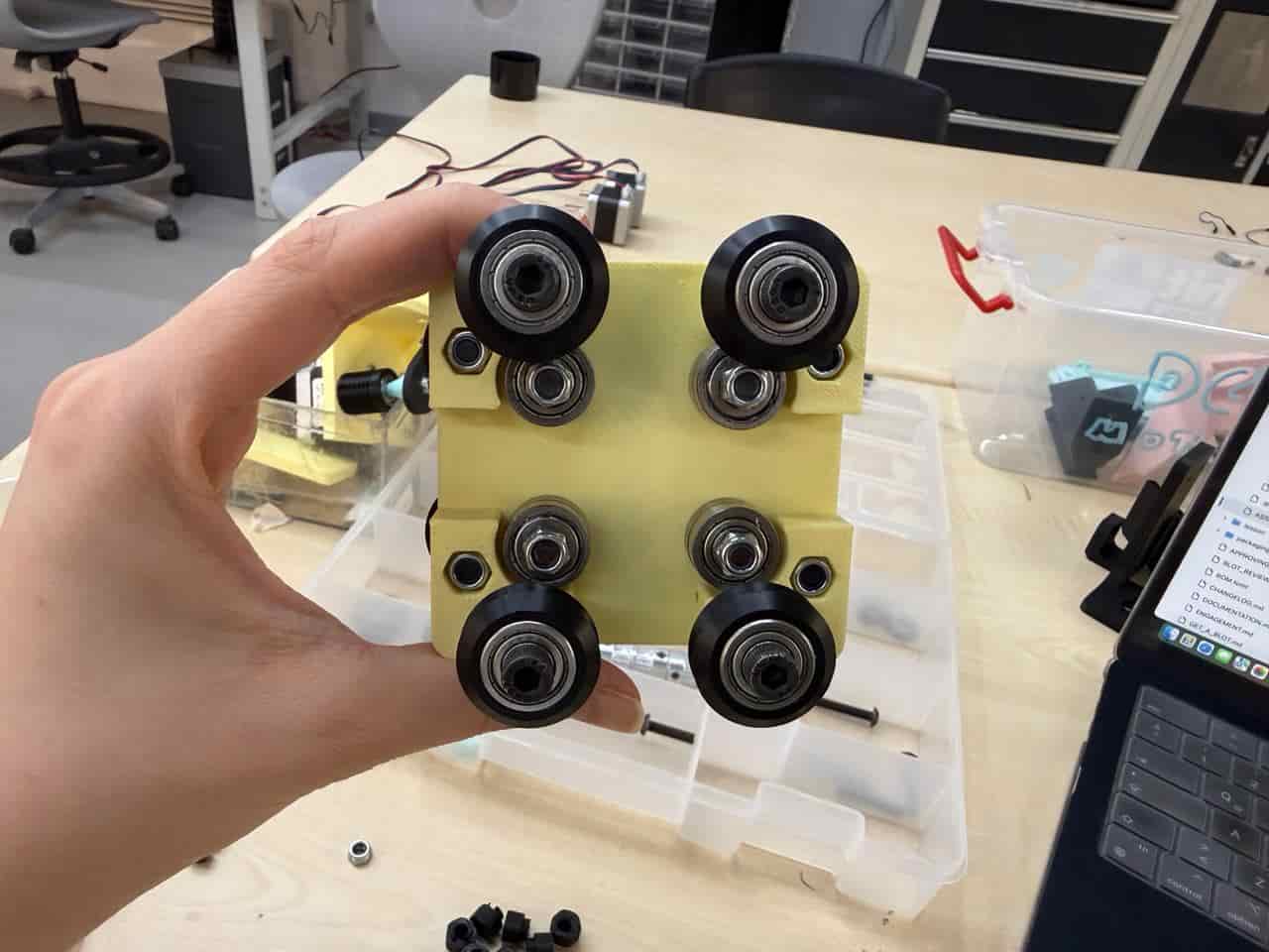
Figure 4. Top side of the carriage showing final wheel alignment.
For the printed rail assembly we used:
Detailed assembly sequence:
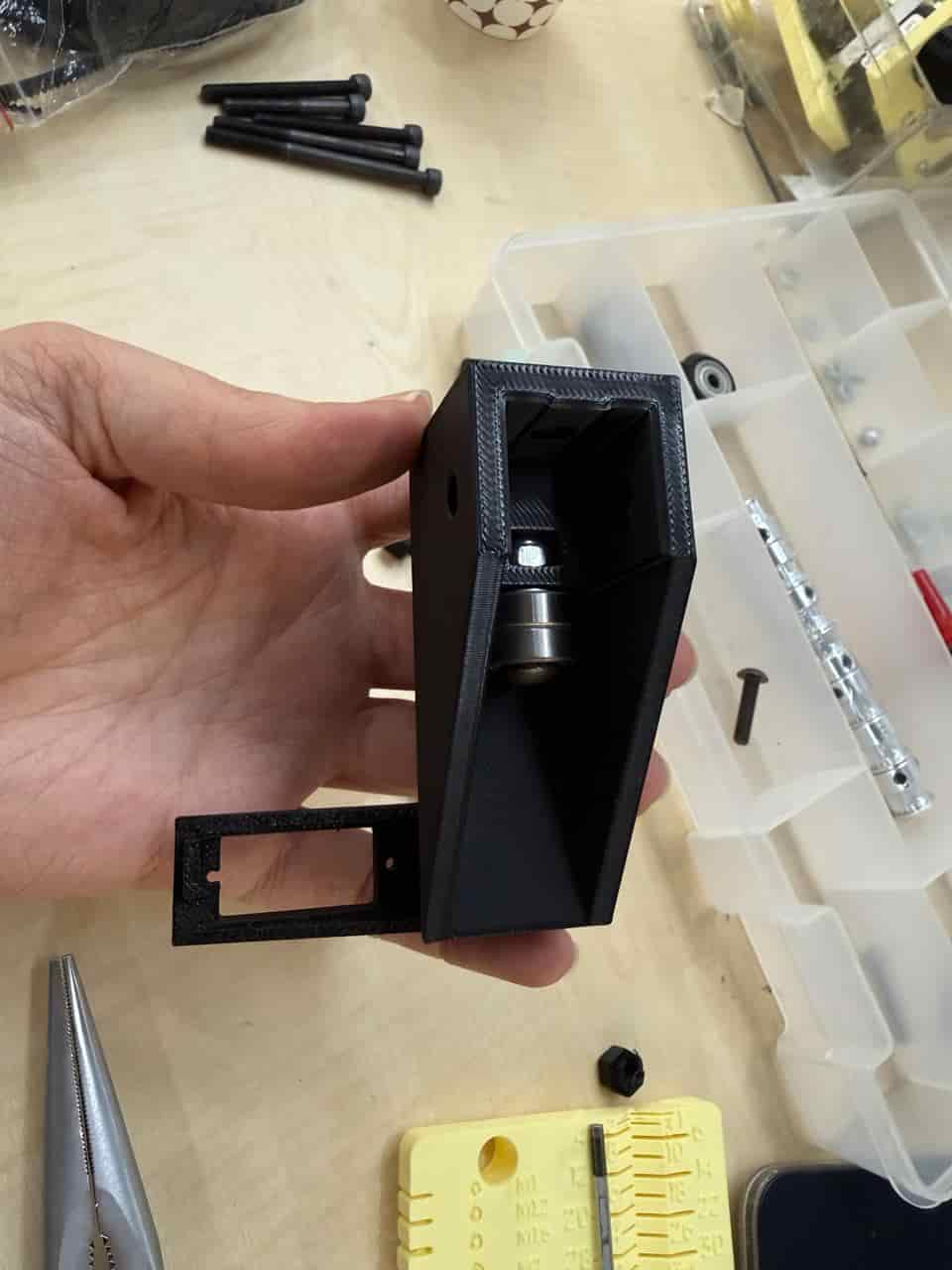
Figure 5. Printed rail with bearing installed inside the housing.
Then we assembled the tool holder using:
Detailed assembly sequence:
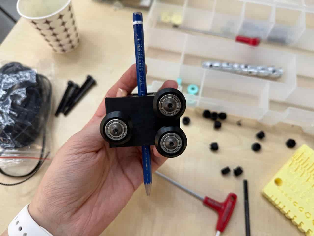
Figure 6. Front view of tool holder with three-wheel arrangement and pen test fit.
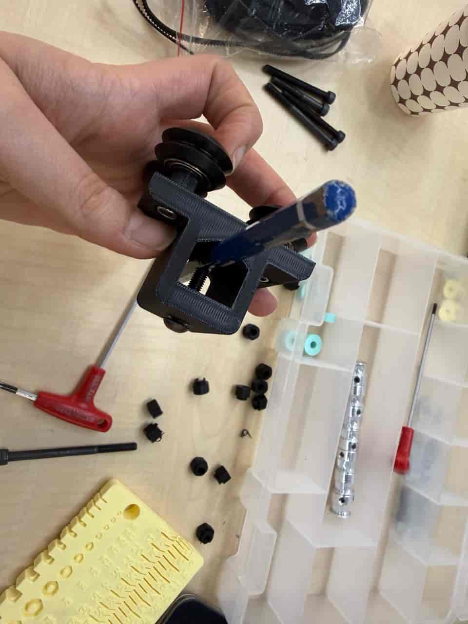
Figure 7. Side view of tool holder showing pen clamp and wheel stack.
We cut two aluminum extrusions to 25 cm:
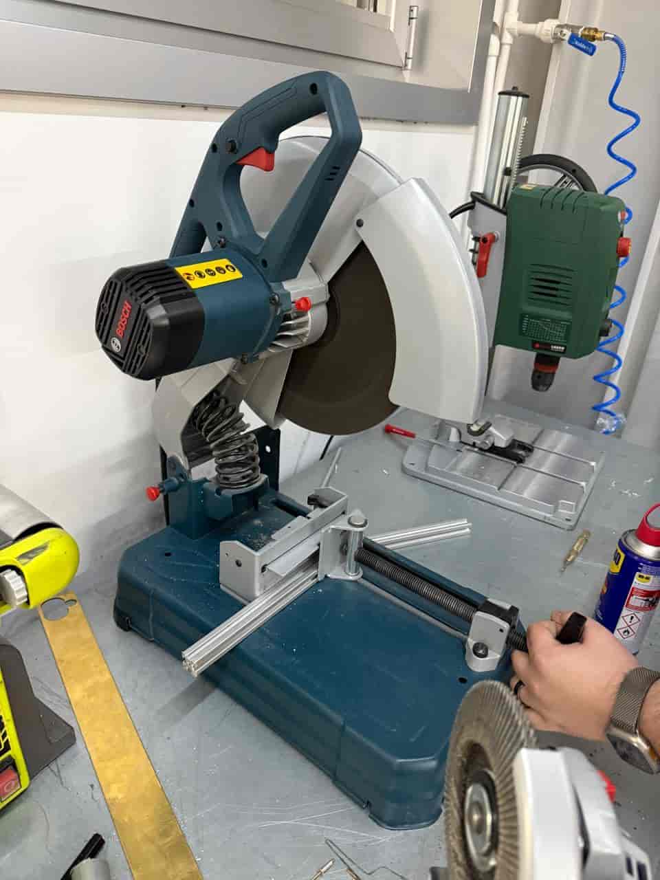
Figure 8. Aluminum extrusion cutting process (view 1).
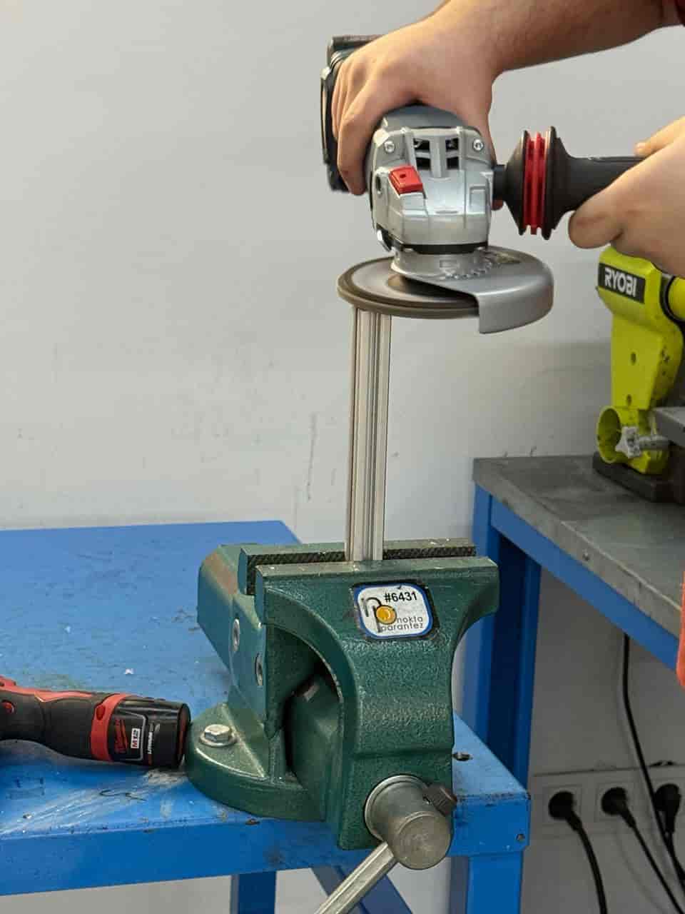
Figure 9. Aluminum extrusion cutting process (view 2).
After checking carriage travel on the extrusions, we assembled the feet with:
We used 3 T-nuts per leg to fix the motor feet.
Detailed assembly sequence:
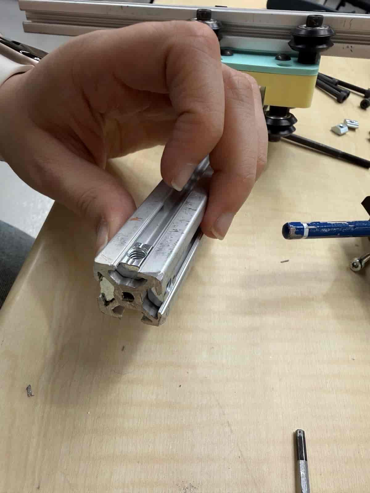
Figure 10. Inserting and positioning T-nuts in extrusion channels.
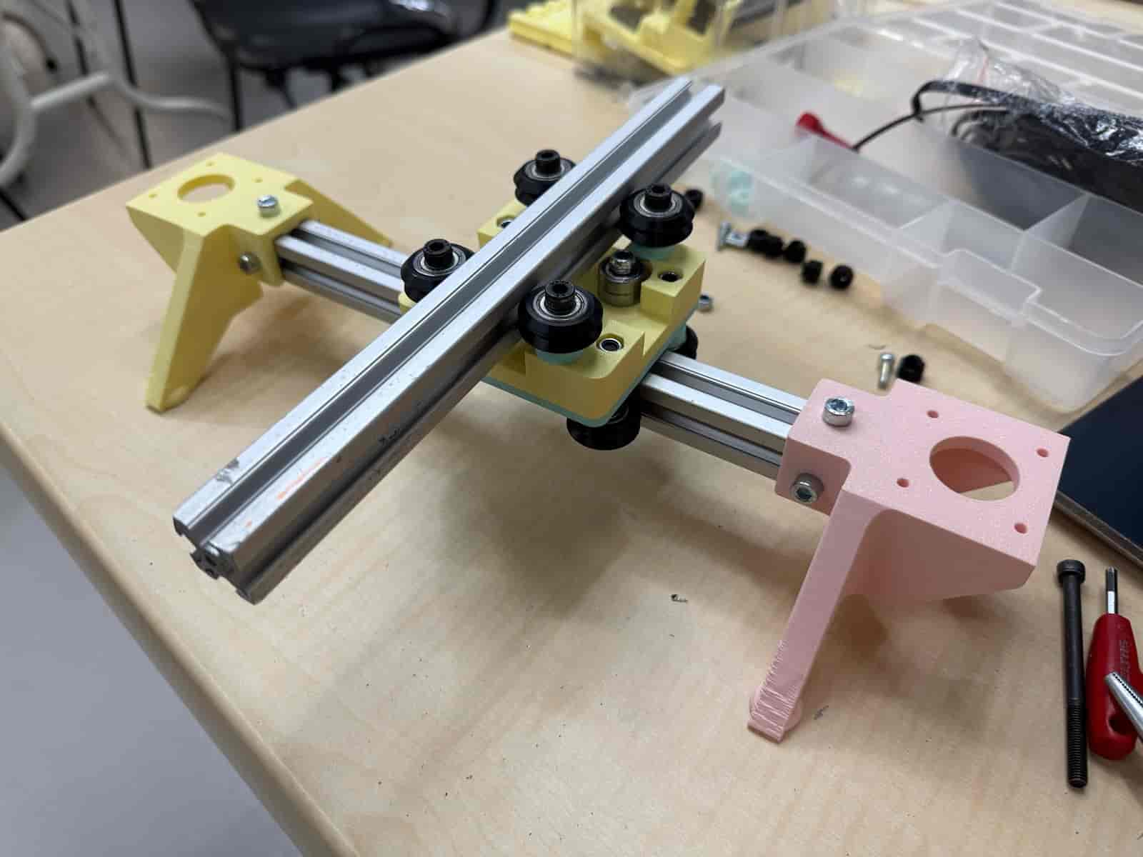
Figure 11. Frame with feet and carriage mounted for travel checks.
For belt routing, we created a loop through the belt fastener, routed through carriage and pulleys, then returned to the fastener and tensioned.
Detailed belt routing and tensioning:
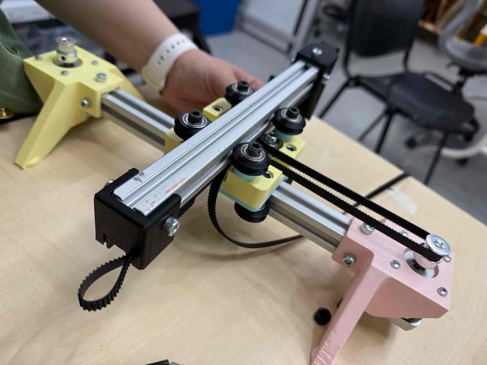
Figure 12. Belt routing through pulley and carriage path.
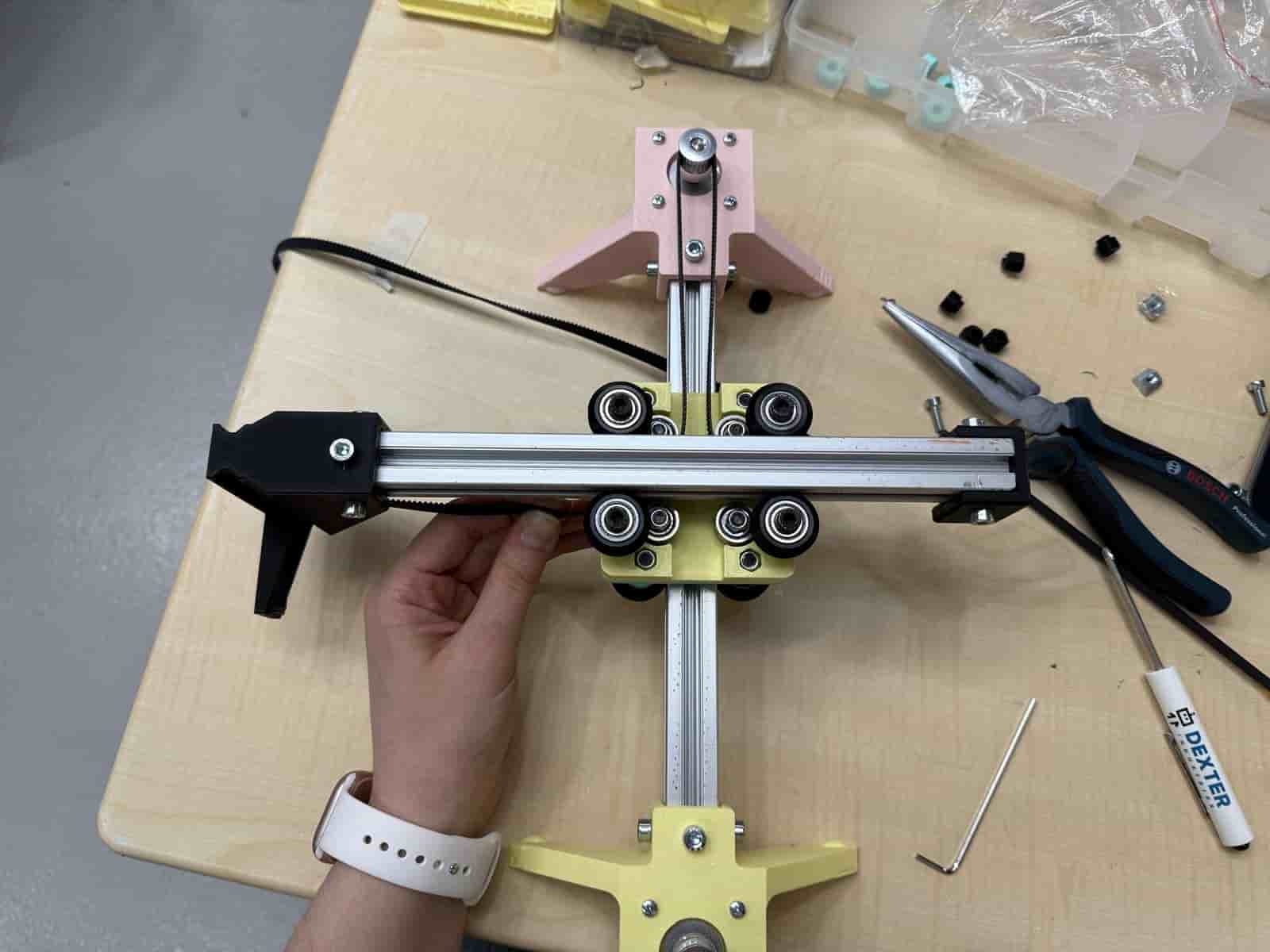
Figure 13. Top view of belt crossing and alignment.
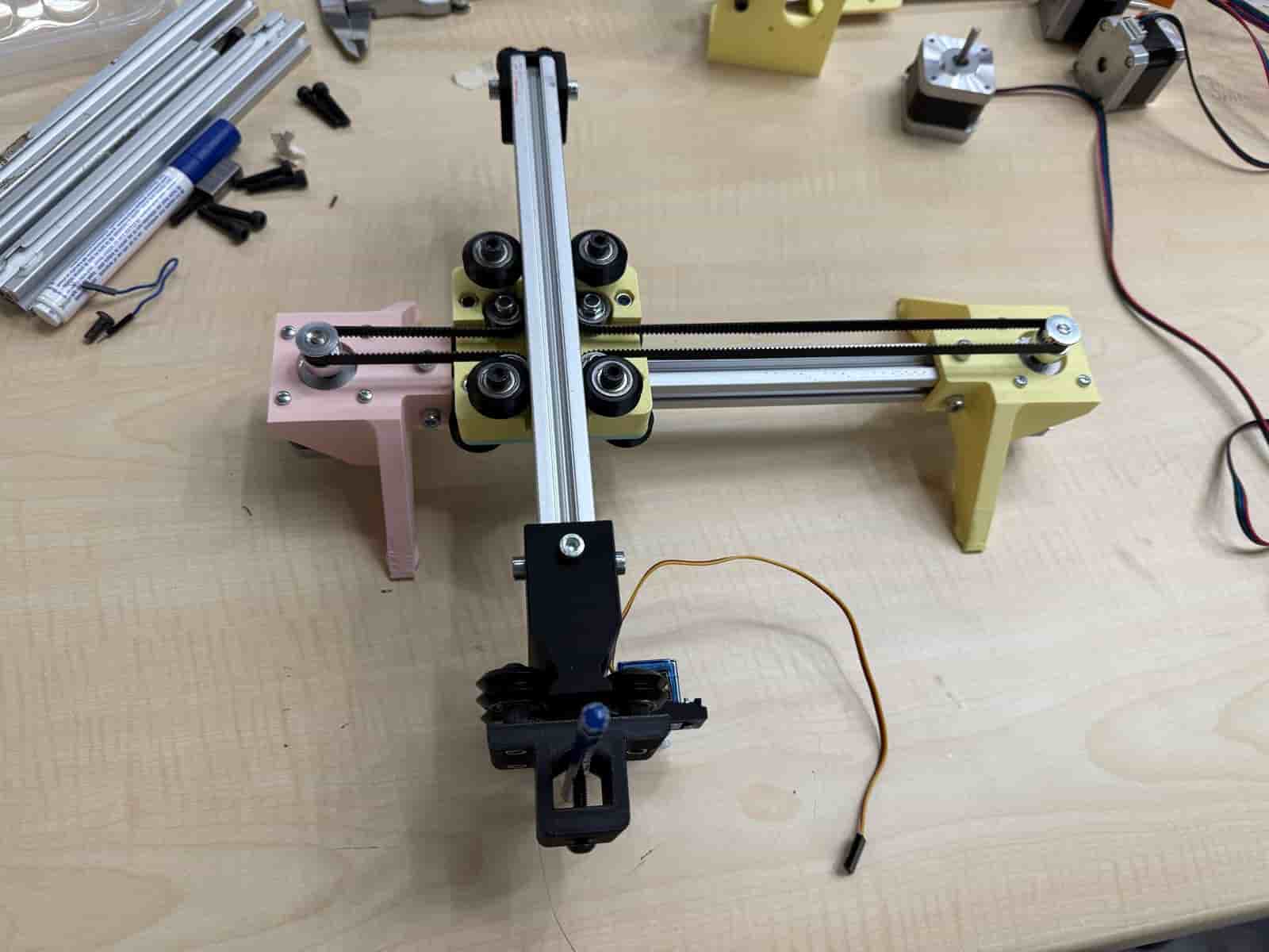
Figure 14. Overall machine assembly after belt installation.
The servo motor on the tool holder provides pen up / pen down behavior (Z-like action for drawing).
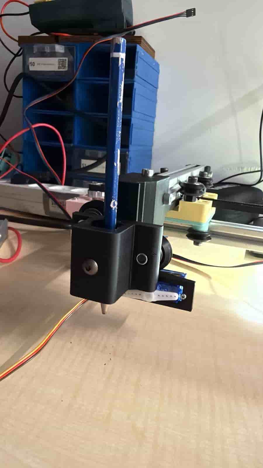
Figure 15. Pen down position for drawing.
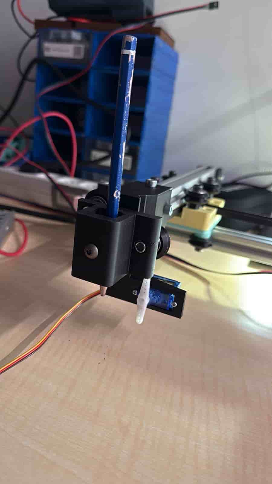
Figure 16. Pen up position for travel moves.
Controller and drivers:
| Signal | Pico Pin | Note |
|---|---|---|
| Motor A/B Direction (X logical DIR) | GP8 | TMC2208 DIR |
| Motor A/B Step (X logical STEP) | GP9 | TMC2208 STEP |
| Motor second channel DIR (Y logical DIR) | GP12 | TMC2208 DIR |
| Motor second channel STEP (Y logical STEP) | GP13 | TMC2208 STEP |
| Pen servo PWM | GP27 | 50 Hz PWM |
Tested working in our setup:
GP8/GP9,GP12/GP13,GP27.Firmware runs on MicroPython and exposes a line-based serial protocol over USB CDC.
COREXY transform (A = X + Y, B = X - Y).ANGLE mode for normal positional servo,CR mode for continuous-rotation servo.
# Servo
SERVO_MODE = "CR"        # "ANGLE" or "CR"
SWAP_PEN = True
PEN_UP_ANGLE = 30
PEN_DOWN_ANGLE = 120
SERVO_STOP_US = 1500
PEN_UP_US = 1400
PEN_DOWN_US = 1600
PEN_UP_MS = 220
PEN_DOWN_MS = 220

# Kinematics
COREXY = True
SWAP_XY = True
MOTOR_A_SIGN = 1
MOTOR_B_SIGN = 1

# Motion speed
DEFAULT_INTERVAL = 1200  # microseconds, lower is faster
X + YX - YIf axis behavior looks wrong:
COREXY,SWAP_XY,MOTOR_A_SIGN / MOTOR_B_SIGN.Motion is intentionally blocking.
Each command executes to completion before next command is processed.
Why we kept it this way:
Commands are case-insensitive, one line each, ending with newline.
OK ...ERR ...#| Command | Function |
|---|---|
X<n> | Relative X move in steps (signed) |
Y<n> | Relative Y move in steps (signed) |
MOVE X<n> Y<n> | Synchronous move; either axis optional |
SPEED <us> | Set step interval in microseconds (>=200) |
STOP | Stop motion and release servo |
WAIT | Process pending servo release, returns OK IDLE |
STATUS | Return machine busy/idle state |
| Command | Function |
|---|---|
PENUP | Lift pen |
PENDOWN | Lower pen |
SERVO <val> | Direct servo value (angle or pulse width) |
SERVO_MODE ANGLE / CR | Switch servo mode |
SERVO_STOP_US <us> | Set neutral pulse in CR mode |
PENUP_US <us> / PENDOWN_US <us> | Tune CR movement pulse |
PENUP_MS <ms> / PENDOWN_MS <ms> | Tune CR movement duration |
PENUP_ANGLE <deg> / PENDOWN_ANGLE <deg> | Tune angle mode positions |
PLOTTER READY
PENUP
OK PEN_UP
MOVE X500 Y500
OK MOVE X=500 Y=500
PENDOWN
OK PEN_DOWN
X1000
OK X 1000
Y-500
OK Y -500
PENUP
OK PEN_UP
Our workflow for testing and drawing:
main.py.PENUPX100, Y100, X-100, Y-100MOVE X200 Y200motor tests
Figure 20. Carriage movement test driven from the software command interface.
SPEED,PENUP_ / PENDOWN_.For reliable start-up, we always:
PENUP first,Calibartion test
Figure 19. Assembly-stage movement test after mounting frame, feet, and carriage.
Pen motion reversed (up/down swapped): toggle SWAP_PEN.
X produces diagonal movement: enable COREXY.
X and Y appear exchanged: set SWAP_XY = True.
One motor direction wrong: invert MOTOR_A_SIGN or MOTOR_B_SIGN.
Motors stall at high speed: increase DEFAULT_INTERVAL (slower), then retune.
Servo jitters: verify power stability and adjust pulse values.
CR servo drifts at stop: tune SERVO_STOP_US around neutral (for example 1490-1520).
This would move the project from a robust weekly prototype to a more complete production-style machine controller.
This section links to the interactive usage/control pages for the HAAC plotter workflow:
./plotter/basic-control.html./plotter/api.html./plotter/work-page.htmlSample usage
Figure 17. Usage site walkthrough video.
Figure 17. Machine Week demo video file preview.
Machine Week forced us to connect mechanical reality and software logic directly.
We observed that many apparent "software bugs" in machine projects are actually system-level interactions between mechanics, wiring, and timing assumptions.
The strongest outcome was getting clean and repeatable drawing only after tuning all subsystems together.
Our main takeaway is that documentation is part of the machine itself: if calibration and decisions are not written clearly, the machine is not truly reproducible.
This group assignment explored local network communication by sending messages between a computer and a mobile phone over shared Wi-Fi, then extending the setup into a simple two-way chat system.
The goal of this group assignment was to send a message between a computer and a mobile device using network communication.
Device: Windows 11 laptop
Role: Python server
Software: PyCharm
Device: iPhone 13
Role: Client
Software: Safari browser
We used a Python-based HTTP server to receive messages sent from a mobile phone over a shared Wi-Fi network. The computer hosted the server, and the phone sent a message using an HTTP request. The message was included in the URL and received by the server.
New Project.NetworkingProject.Create.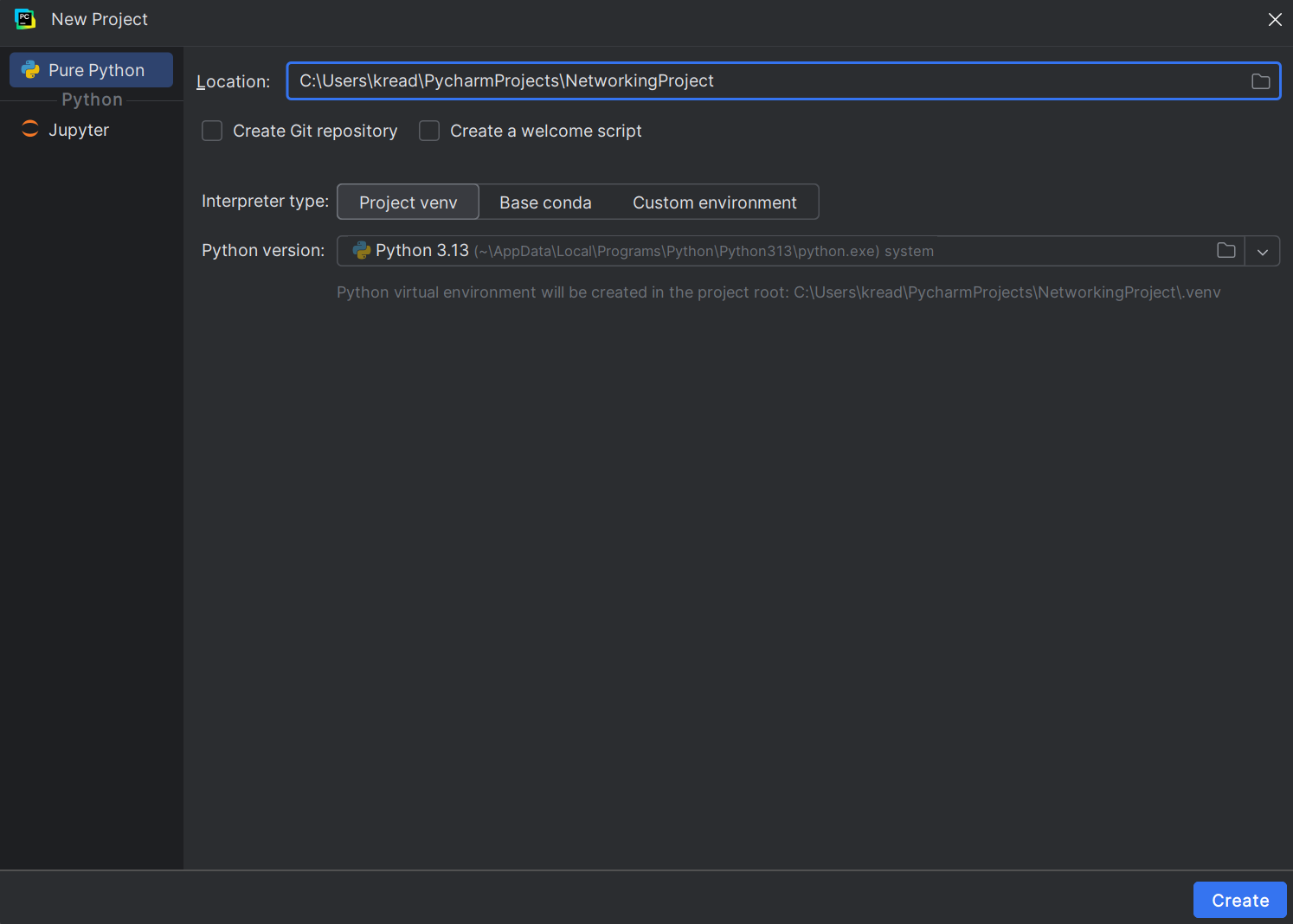
+ sign at the top of the left panel.New Python File.server.This creates server.py.
Paste the following code into server.py:
from http.server import BaseHTTPRequestHandler, HTTPServer

class MyHandler(BaseHTTPRequestHandler):
    def do_GET(self):
        message = self.path[1:]  # remove "/"
        print("Received message from iPhone:", message)
        self.send_response(200)
        self.end_headers()
        self.wfile.write(b"Message received!")

server = HTTPServer(("0.0.0.0", 8000), MyHandler)
print("Server running...")
server.serve_forever()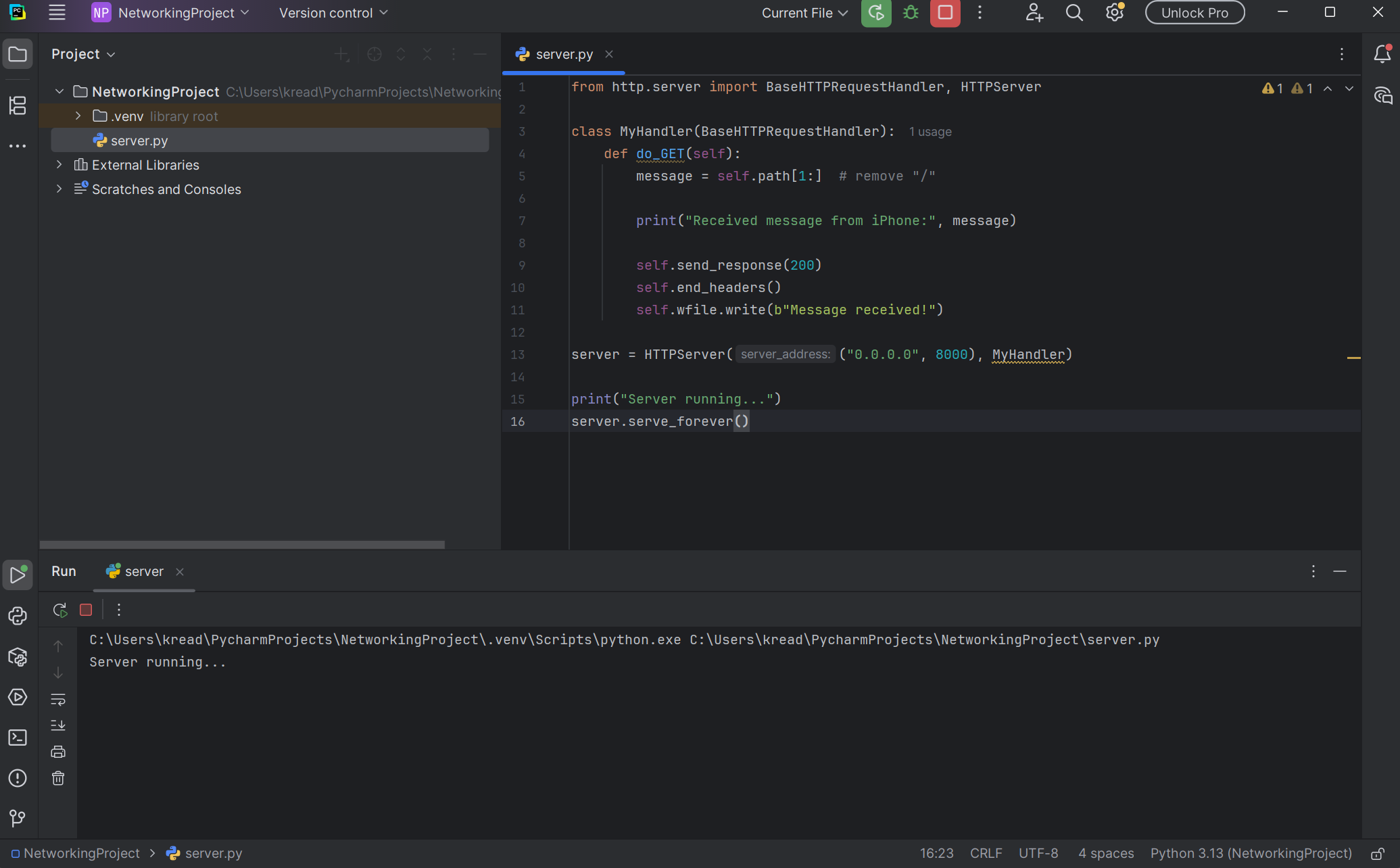
Run 'server'.You should see Server running... at the bottom.
ipconfig.192.168.X.X.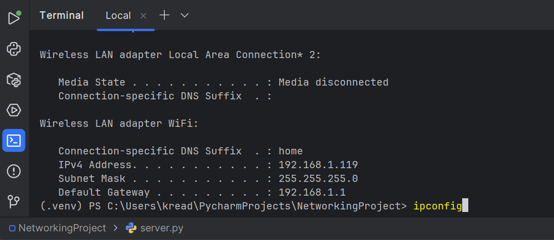
ipconfig.http://192.168.x.x:8000/HelloFromiPhoneThen enter the website.
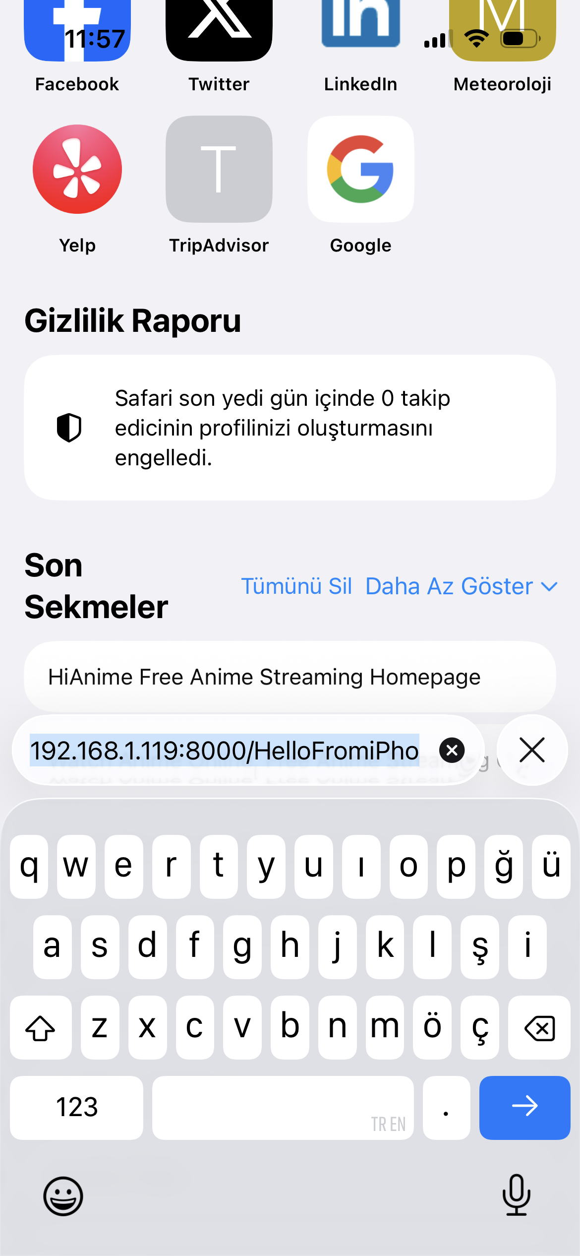
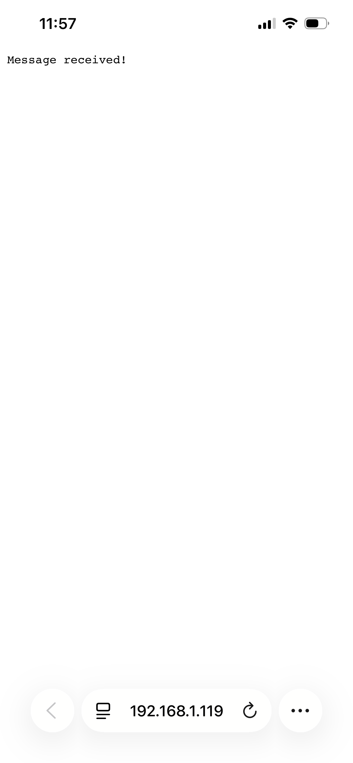
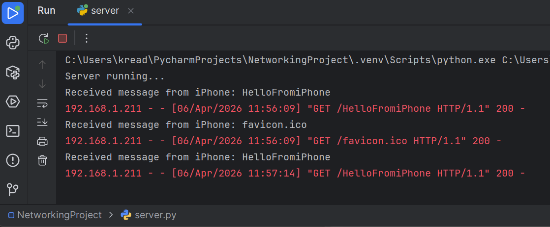
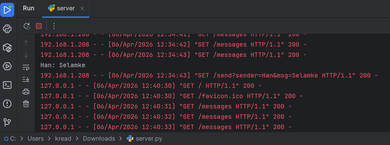
In the PyCharm console, we could see:
Received message from iPhone: HelloFromiPhoneThis confirmed that the system worked successfully.
Instead of just sending a message, we stored messages on the server and allowed both devices to send and receive messages. In this way, the project became a mini chat system.
In PyCharm, replace the previous code with the following:
from http.server import BaseHTTPRequestHandler, HTTPServer
import urllib.parse
messages = [] # shared message list
class MyHandler(BaseHTTPRequestHandler):
def do_GET(self):
global messages
if self.path.startswith("/send"):
query = urllib.parse.urlparse(self.path).query
params = urllib.parse.parse_qs(query)
msg = params.get("msg", [""])[0]
sender = params.get("sender", ["Unknown"])[0]
full_msg = f"{sender}: {msg}"
messages.append(full_msg)
print(full_msg)
self.send_response(200)
self.end_headers()
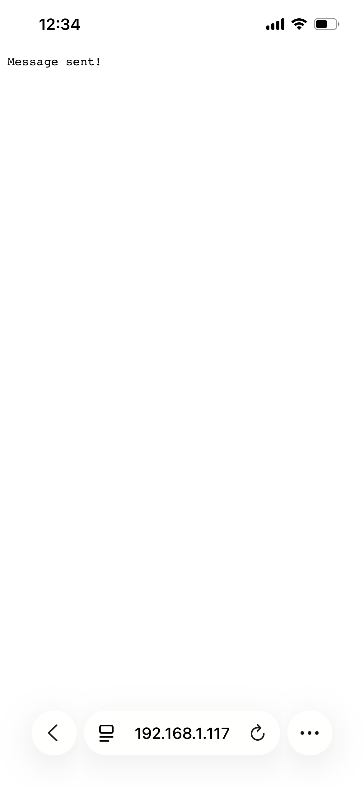
self.wfile.write(b"Message sent!")
elif self.path.startswith("/messages"):
self.send_response(200)
self.end_headers()
response = "\n".join(messages)
self.wfile.write(response.encode())
else:
self.send_response(200)
self.send_header("Content-type", "text/html")
self.end_headers()
html = f"""
<html>
<body>
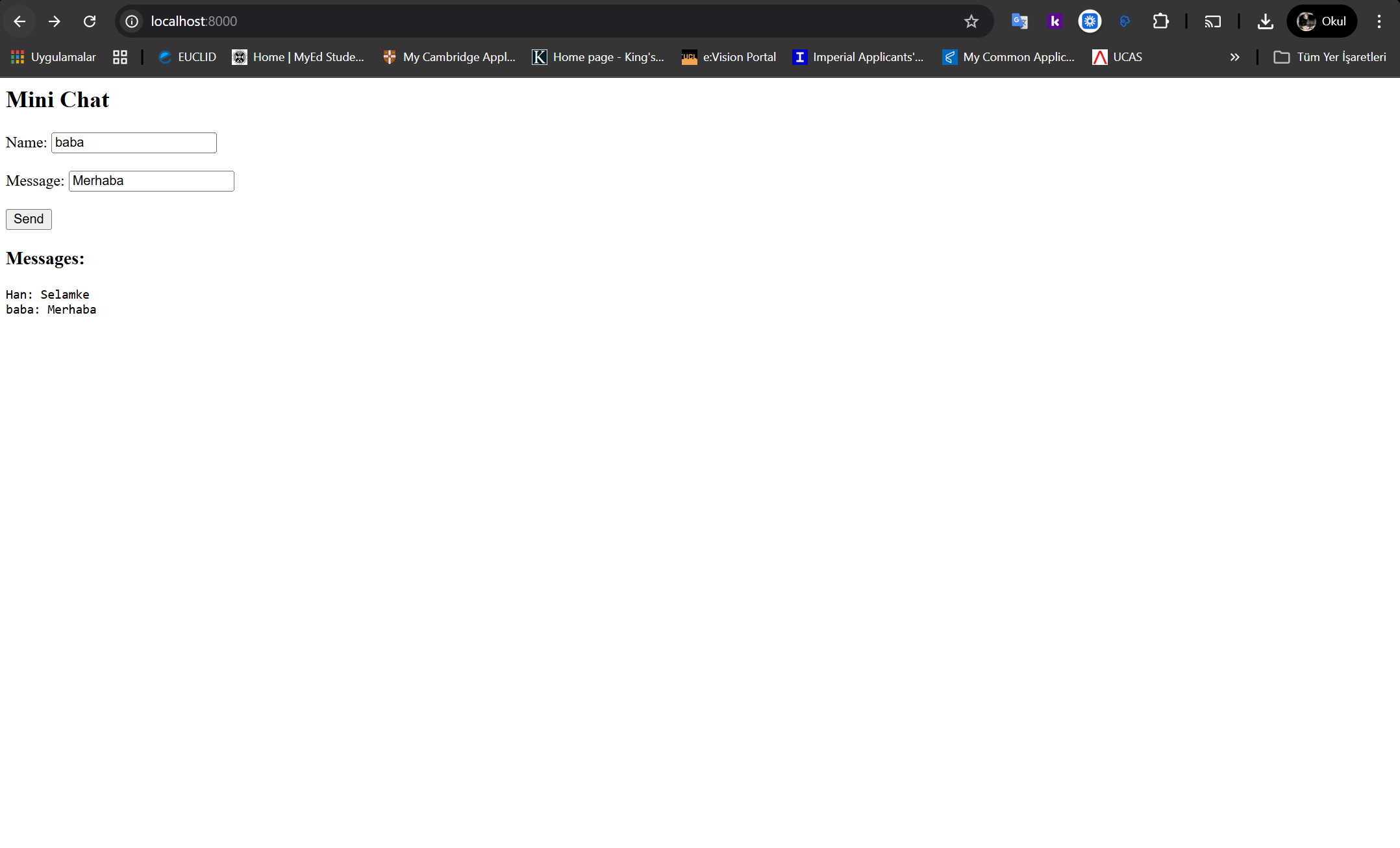
<h2>Mini Chat</h2>
<form action=\"/send\">
Name: <input type=\"text\" name=\"sender\"><br><br>
Message: <input type=\"text\" name=\"msg\"><br><br>
<input type=\"submit\" value=\"Send\">
</form>
<h3>Messages:</h3>
<pre id=\"chat\"></pre>
<script>
async function loadMessages() {
let res = await fetch('/messages');
let text = await res.text();
document.getElementById('chat').innerText = text;
}
setInterval(loadMessages, 1000);
</script>
</body>
</html>
"""
self.wfile.write(html.encode())
server = HTTPServer(("0.0.0.0", 8000), MyHandler)
print("Chat server running...")
server.serve_forever()
Click Run in PyCharm. You should see:
Chat server running...On the computer browser:
http://localhost:8000On the iPhone in Safari:
http://YOUR_IP:8000Then send messages between both devices.
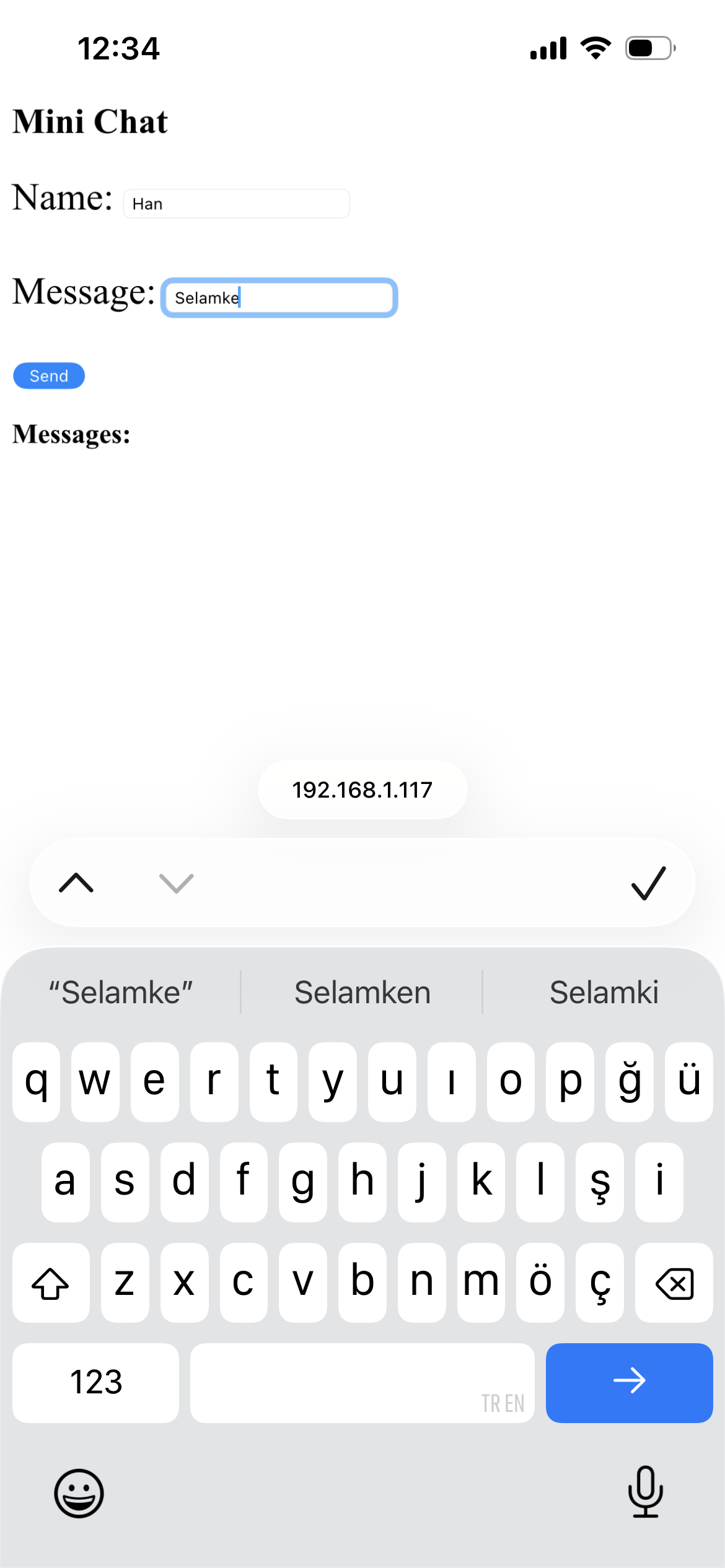
After clicking Send on the phone, the chat interface and message confirmation appeared.
Make sure that:
If the iPhone shows “This site can’t be reached”, check:
In this assignment, we learned how communication between devices works using networking concepts. We understood how a computer can act as a server while a mobile phone acts as a client.
We also learned how HTTP requests function and how data can be transmitted through a URL. Writing and running the Python code helped us understand how servers handle incoming requests.
One difficulty we faced was finding the correct IP address and ensuring both devices were connected to the same Wi-Fi network. After solving these issues, the system worked successfully.
Later, we extended the system from one-way communication into a two-way communication system. A shared message list was implemented on the server, allowing both the computer and the mobile device to send and receive messages dynamically.
Overall, this project improved our understanding of networking, especially client-server communication and data transmission over a local network.